Any regular views may notice that there are a few more photo links.
I had a bit of a sort out of the photo's and have put them in to 10 basic categories.
Ignore the Photo Bucket cr#p and feel free to have a look.
Please let me know if any of the links don't work.
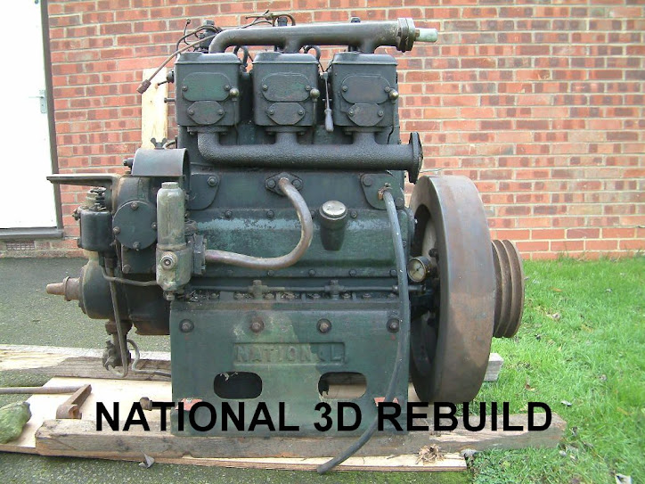
Engine porn at its best!
Edited to add:
A gentle slap on the hand from Sarah (see comments). There are a couple of acknowledgements I should really add.
The photos of the 'National Works' are courtesy of Sarah (NB Warrior). See: http://d3national.blogspot.com/2007/12/national-works-aston-under-lyne.html
The 'Engine Pre strip down' and 'Initial strip down' are courtesy of Lionel Knight: http://d3national.blogspot.com/2007/12/well-i-think-i-may-have-added-some.html
I think the rest are mine.
Sunday, 25 May 2008
Wednesday, 21 May 2008
End Bed
Well, it was a weekend of cutting, grinding and welding. A bit of a change from degreasing, cleaning, stripping and wire brushing!


The result - an engine bed all fabricated up and ready for the re-build.
Its basically fabricated out of 75mm x 150mm channel (that's 6" x 3" in old money). The ultimate plan is to rebuild the engine from the bottom up, direct on to the bed plate. Get the gear box setup and aligned and once all finished and tested, the whole shooting match get transported up to the boat builder and welded in to place direct to the base plate.
Once fabricated, it was time to drill the holes for the mounting bolts. 21" apart and 20" along, 3/4" holes. Using the old adage of measure several times and drill only once, checking the diagonals to ensure they where all perfectly aligned, it drilled some 4mm pilot holes.
Before stepping up to eventually drill the full 3/4" holes; I 'dropped' the bottom end with the mounting legs on to the frame. Theoretically, the pilot holes should have been right in the centre of existing 3/4" leg holes.
Were they buggery!
Remove the bottom end, double check all of the measurements on the bed. Yes, everything was true and square. 21" x 20" with equal diagonals.
Check the engine legs (not an easy task with 2/3 cwt of engine bed floating in mid air on the hoist). Hole centres are 21" x 20". Equal diagonals - NO! The engine legs are pi##ed.
Take the legs off the Crankcase. Yep, they're fine. All of the original locating dowels are in place and true and the legs cannot be put on the 'wrong side' because the dowel won't allow it.
Put the legs back on, bolt them all. Re-check the measurements. Still askew!
Because the pilot holes have been drilled, the only answer now is to get a 3/4" hole saw and (after clamping the engine base to the bed) drill down through the leg holes and straight in to the base.
So much for the science of measuring and drilling as per the 'factory measurements'.
Hey Ho!
Monday, 12 May 2008
Governor and speed control
One of the big outstanding issues is the governor arrangement on the engine. The majority of Nationals and Russell Newbery engines have horizontal governors. Not the case in my engine.
It has its own casing that is mounted on the end of the timing casing and is a vertical arrangement. The centrifugal governor weights are at the top of a vertical shaft (with the connections to the speed controller and the fuel pump), whilst the oil pump is at the bottom.

To be fair, at the moment its a bit of an 'un-known' as to how well it will control engine speed throughout the required range of 250 - 1,000 rpm.
If the engine originated from a generating set, it is almost certainly set up to run at constant speed. The governor then adjusts the fuel rack to ensure a constant speed irrespect of load on the alternator.
On my linkage from the governor to the fuel pump there is a lever and cam arrangement. From what I can work out, this appears to be a rudimentary speed control. But how redamentary is it?

One school of thought is that it may be a speed controller to slightly adjust the 'constant running speed' for frequency control. Say +/- 20 rpm. If that is the case, it may prove difficult to control the lower speed ranges required (but not impossible!).
The other school of though is that it is full range speed controller. This is the one I like because it will work perfectly - forever the optimist! A few clues have revealed themselves:
1. All of the industrial generator sets that I have seen usually have the engine plate marked up as: '##hp at ####rpm' or 'operating speed: ####rpm', etc. My engine plate just gives Engine Type and Engine Number.
2. When I cleaned up the cam linkage it had two marks on it with arrows to a fixed mark. One said 'WORK', the other was unmarked (but why have it?). I'm hoping the unmarked arrow is 'idle'.

To be honest, until the Black Beast is fired up, I'll not know (unless anyone else knows differently??). Even if it is a constant speed unit, a bit a playing with the spring tension and cam profiles should be able to sort it (there goes the optimist again!).
Needless to say, it is now subject if stripping down, degreasing, cleaning, wire brushing, painting etc, etc.
Tuesday, 6 May 2008
Work and Play
The bank holiday weekend saw a little more progress on the engine combined with a bit of engine orientated socialising.
Anyway, The sunshine saw me wheeling out the engine, putting together the 2 tonne engine hoist and lift up the flywheel to offer it up to the crank. Did it fit? Like a glove! The shoulder on the crank matched the recess of the flywheel, as did the bolt holes and diameters.

I then took various photograph and measurements so that I could look at working out how to mount the starter motor bracket (once it was fabricated - which is another job!).
Sunday saw me pottering up to the Russell Newbery Works open day at Daventry. I wont bore you with to much detail, but rest assured that most of the talk was around RN's, but the National owners (3 of us I think) were present too!
Sarah on NB Warrior has more detail on her blog:
Note the cock up on the hand over of the pistons and liners - DOH!
What of the engine?
My previous post was about the template for the engine bed. Whilst I was thinking about ordering steel, I also thought about how I would eventually mount the starter motor and fabricate a suitable mounting bracket. The engine was originally hand start only and had a large industrial flywheel with no ring gear. Not to much of a problem as the engine came with a 'marine flywheel that should fit'.
One thing I had never done was check to see if it did. Probably because both of the two mating components (flywheel & crankshaft) were so damn heavy to shift around.
Whilst talking about this, anyone reading ye olde blogg who is considering rebuilding any engine of this ilk, please take in to account the weight of components that you will have to 'move around'. The flywheel is about 2 cwt, the block 2.75cwt, the crank is over 4' long and even things like timing covers make you grunt when you lift them. Every thing takes 3 times as long and twice as much effort!
Don't be put off though, its great fun (in a fairly masochistic sense).
Anyway, The sunshine saw me wheeling out the engine, putting together the 2 tonne engine hoist and lift up the flywheel to offer it up to the crank. Did it fit? Like a glove! The shoulder on the crank matched the recess of the flywheel, as did the bolt holes and diameters.
I then took various photograph and measurements so that I could look at working out how to mount the starter motor bracket (once it was fabricated - which is another job!).
Looking at the above photo you would expect the paint to be in fairly poor condition. Over about 30% of the area it was, the remaining 70% it was stuck like poo to a blanket. I spent a whole day stripping several layers of paint off the flywheel ready for the usual wirebrushing etc, etc. Again a job complicated by having to move a 2 cwt lump of metal around.
Sunday, 27 April 2008
Engine Bed
I've stopped procrastinating and made a decision.
I’m going to mount the engine: flywheel at the forward end and the gearbox at the rear. If I took the propshaft of off the flywheel end, I had a 4" stub of crankshaft at the non-flywheel end to mount any drive pulleys for alternator(s), water pumps etc. Where as the flywheel has numerous holes to through mount an extension shaft to run anything.
Flange of off the 4" stub, flexible coupling, then into the gearbox. The gearbox mounted in its own frame just behind the engine and all bolted to the same engine bed.
I’ve also decided to wait for the new PRM 260 with a 1:1 ratio as well. Its currently being tested (still no timeframes for ‘launch to the market’) but it will be ideal for my requirements. 21" standard prop and 1 ½" shaft/stern gear.
Now that the decision is made, my thoughts turned to an engine bed.
My plan is to set up whole engine up on an engine bed as part of the rebuild process. Everything would then be bolted down and aligned etc before the whole thing was supplied to the boat builder. All that would then be required would be to weld the engine bed to the base plate.
The engine is sitting on a 2 tonne trolley during the rebuild and it has an excellent flat surface. I wanted to make a template so that I could confirm all of the dimensions, hole centres and crank alignment dimensions.
First thing was to get every thing of off the trolley and give it a good clean. Next I stuck sheets of A3 paper all over it and then carefully placed the engine back on it. It was then a case of marking around the engine feet and the mounting holes.
The next thing was marking the ends of the crankshaft to get the centreline. I did this by carefully ‘plumb-lining’ from the ends of the crank.

Lift everything off, and hey presto, one engine bed template.

Knowing the gearbox dimensions and allowing some space for the coupling in between, I have estimated the engine bed to be approximately 5’ long. In practice it may be a bit shorter, but its easy to cut a bit off!
The engine bed will now be constructed out of 3 x 6 ‘C’ section (75mm x 150mm in new money). A quick call to my local steel stockist confirmed 13’ of channel would be a shade over £100.
I’m going to mount the engine: flywheel at the forward end and the gearbox at the rear. If I took the propshaft of off the flywheel end, I had a 4" stub of crankshaft at the non-flywheel end to mount any drive pulleys for alternator(s), water pumps etc. Where as the flywheel has numerous holes to through mount an extension shaft to run anything.
Flange of off the 4" stub, flexible coupling, then into the gearbox. The gearbox mounted in its own frame just behind the engine and all bolted to the same engine bed.
I’ve also decided to wait for the new PRM 260 with a 1:1 ratio as well. Its currently being tested (still no timeframes for ‘launch to the market’) but it will be ideal for my requirements. 21" standard prop and 1 ½" shaft/stern gear.
Now that the decision is made, my thoughts turned to an engine bed.
My plan is to set up whole engine up on an engine bed as part of the rebuild process. Everything would then be bolted down and aligned etc before the whole thing was supplied to the boat builder. All that would then be required would be to weld the engine bed to the base plate.
The engine is sitting on a 2 tonne trolley during the rebuild and it has an excellent flat surface. I wanted to make a template so that I could confirm all of the dimensions, hole centres and crank alignment dimensions.
First thing was to get every thing of off the trolley and give it a good clean. Next I stuck sheets of A3 paper all over it and then carefully placed the engine back on it. It was then a case of marking around the engine feet and the mounting holes.
The next thing was marking the ends of the crankshaft to get the centreline. I did this by carefully ‘plumb-lining’ from the ends of the crank.
Lift everything off, and hey presto, one engine bed template.
Knowing the gearbox dimensions and allowing some space for the coupling in between, I have estimated the engine bed to be approximately 5’ long. In practice it may be a bit shorter, but its easy to cut a bit off!
The engine bed will now be constructed out of 3 x 6 ‘C’ section (75mm x 150mm in new money). A quick call to my local steel stockist confirmed 13’ of channel would be a shade over £100.
Monday, 14 April 2008
Covers etc
Although I haven't been blogging much of late, things have been happening (apart from liner measuring)


I thought that I had better show a little bit more of the progress.
The next string of shots are really before and after shots. Before being, various components wire brushes and cleaned ready for painting. The after being similar shots of the same components with paint on them.
First up is the 'Airbox'. This sits on the side of the block and is the common air filter box for all three cylinders. The individual intakes for each cylinder draw air out of one of the three elongated slots. The multiple slots face downward toward the bottom of the engine. The Airbox is another component which I found the engine number stamped on it. Each of the outlets were also stamped 1, 2 & 3 respectively as well. The two studs sticking out of the side of the box are for mounting the fuel filter on.
The frame below is located inside the Airbox and (allegedly) holds the wad of horse hair together.
I think I'll cheat and use moderns synthetic filter material.
Next up is a few cover plates. Top left in the photo is the crank end cover for the non flywheel end. Top right is an inspection plate for the governor casing. The bottom two are blanking plates for cylinders 1 & 3, waterside of the block.
Next up are a series of pictures showing the cylinder block inspection doors. Obviously one door on either side of the engine. One having the oil filler point.
At some point in time I'm going to have to make joints for all of these various covers. Break out the Klingerite and wad punches!
Saturday, 12 April 2008
The Liner Wars (and Pistons)
Not so much a war - but I had to make a decision about the liners for the re-build.
NB Warrior kindly donated their old liners and pistons to see if they were better than mine. Now it was time to see which ones where the best.
There is no real alternative but to use good old fashioned measuring. And the measuring device – an internal micrometer of course.
Along came the evening when I had the house to myself. The liners duly found themselves on the kitchen table (hence the house to myself) all in a nice neat row.

Now I know, there’s only 5. The left hand three being mine the right hand two being ex’ Warrior (one never made it http://nbwarrior.blogspot.com/2008/03/even-goldfish-can-count-to-three.html)
The first measurement was the very top and very bottom of a liner. This confirms the original (non worn) diameter. Measurements are taken at 90 deg’ at each point to check to see how oval the bore is.

The reference measurements on my original liners was 4.125" (4.1/8th"). All three were spot-on.
Next was measuring the ‘worn area’. I was pleasantly surprised to find each liner gave the same readings of wear:
Longitudinally: 4.128 (3 thou wear). Transverse: 4.130 (5 thou wear) at the top of the stroke and slowly tapering out down to the original diameter as you went down the stroke. A max of 5 thou wear and 2 thou oval. Not a bad result.

Next up was the two (of three) liners from Warrior. The first difference was the original diameter. 4.135" top and bottom. They were both 10 thou oversize. The remaining measurements confirmed that the overall wear was of a similar pattern to mine but 1 thou less on each measurement.
The original factory spec was 4.1/8th" bore and 6" stroke. It would appear the Warriors liners, although slightly less worn than mine, have had a 10 thou re-bore in a previous part of their life.
Which ones to use – well, mine of course. I’ll have a chat with the machine shop, but I think a 5 thou hone from the original diameter to remove the oval bore and "the jobs a good un".
An examination of the pistons found them all to be of a similar condition. Mine have got the oil rings well and truly jammed in and are yet to be eased out. Both sets of pistons have slightly scuffed skirts, but nothing much to worry about. The ring groves are still tight and true. Overall, either set could be recycled with no problems.

All its going to take now is a trip over to Warrior to re-unite them with their 'bits'. Any excuse to see another National will do!
A useful exercise - and thanks to Jim & Sarah for the offer of their old liners and pistons.
NB Warrior kindly donated their old liners and pistons to see if they were better than mine. Now it was time to see which ones where the best.
There is no real alternative but to use good old fashioned measuring. And the measuring device – an internal micrometer of course.
Along came the evening when I had the house to myself. The liners duly found themselves on the kitchen table (hence the house to myself) all in a nice neat row.
Now I know, there’s only 5. The left hand three being mine the right hand two being ex’ Warrior (one never made it http://nbwarrior.blogspot.com/2008/03/even-goldfish-can-count-to-three.html)
The first measurement was the very top and very bottom of a liner. This confirms the original (non worn) diameter. Measurements are taken at 90 deg’ at each point to check to see how oval the bore is.
The reference measurements on my original liners was 4.125" (4.1/8th"). All three were spot-on.
Next was measuring the ‘worn area’. I was pleasantly surprised to find each liner gave the same readings of wear:
Longitudinally: 4.128 (3 thou wear). Transverse: 4.130 (5 thou wear) at the top of the stroke and slowly tapering out down to the original diameter as you went down the stroke. A max of 5 thou wear and 2 thou oval. Not a bad result.
Next up was the two (of three) liners from Warrior. The first difference was the original diameter. 4.135" top and bottom. They were both 10 thou oversize. The remaining measurements confirmed that the overall wear was of a similar pattern to mine but 1 thou less on each measurement.
The original factory spec was 4.1/8th" bore and 6" stroke. It would appear the Warriors liners, although slightly less worn than mine, have had a 10 thou re-bore in a previous part of their life.
Which ones to use – well, mine of course. I’ll have a chat with the machine shop, but I think a 5 thou hone from the original diameter to remove the oval bore and "the jobs a good un".
An examination of the pistons found them all to be of a similar condition. Mine have got the oil rings well and truly jammed in and are yet to be eased out. Both sets of pistons have slightly scuffed skirts, but nothing much to worry about. The ring groves are still tight and true. Overall, either set could be recycled with no problems.
All its going to take now is a trip over to Warrior to re-unite them with their 'bits'. Any excuse to see another National will do!
A useful exercise - and thanks to Jim & Sarah for the offer of their old liners and pistons.
Subscribe to:
Posts (Atom)