Sunday 27 April 2008

Engine Bed

I've stopped procrastinating and made a decision.

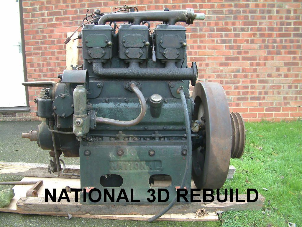
I’m going to mount the engine: flywheel at the forward end and the gearbox at the rear. If I took the propshaft of off the flywheel end, I had a 4" stub of crankshaft at the non-flywheel end to mount any drive pulleys for alternator(s), water pumps etc. Where as the flywheel has numerous holes to through mount an extension shaft to run anything.

Flange of off the 4" stub, flexible coupling, then into the gearbox. The gearbox mounted in its own frame just behind the engine and all bolted to the same engine bed.

I’ve also decided to wait for the new PRM 260 with a 1:1 ratio as well. Its currently being tested (still no timeframes for ‘launch to the market’) but it will be ideal for my requirements. 21" standard prop and 1 ½" shaft/stern gear.

Now that the decision is made, my thoughts turned to an engine bed.


My plan is to set up whole engine up on an engine bed as part of the rebuild process. Everything would then be bolted down and aligned etc before the whole thing was supplied to the boat builder. All that would then be required would be to weld the engine bed to the base plate.

The engine is sitting on a 2 tonne trolley during the rebuild and it has an excellent flat surface. I wanted to make a template so that I could confirm all of the dimensions, hole centres and crank alignment dimensions.


First thing was to get every thing of off the trolley and give it a good clean. Next I stuck sheets of A3 paper all over it and then carefully placed the engine back on it. It was then a case of marking around the engine feet and the mounting holes.

The next thing was marking the ends of the crankshaft to get the centreline. I did this by carefully ‘plumb-lining’ from the ends of the crank.


Lift everything off, and hey presto, one engine bed template.


Knowing the gearbox dimensions and allowing some space for the coupling in between, I have estimated the engine bed to be approximately 5’ long. In practice it may be a bit shorter, but its easy to cut a bit off!

The engine bed will now be constructed out of 3 x 6 ‘C’ section (75mm x 150mm in new money). A quick call to my local steel stockist confirmed 13’ of channel would be a shade over £100.
Monday 14 April 2008

Covers etc

Although I haven't been blogging much of late, things have been happening (apart from liner measuring)

I thought that I had better show a little bit more of the progress.
The next string of shots are really before and after shots. Before being, various components wire brushes and cleaned ready for painting. The after being similar shots of the same components with paint on them.

First up is the 'Airbox'. This sits on the side of the block and is the common air filter box for all three cylinders. The individual intakes for each cylinder draw air out of one of the three elongated slots. The multiple slots face downward toward the bottom of the engine. The Airbox is another component which I found the engine number stamped on it. Each of the outlets were also stamped 1, 2 & 3 respectively as well. The two studs sticking out of the side of the box are for mounting the fuel filter on.


The frame below is located inside the Airbox and (allegedly) holds the wad of horse hair together.
I think I'll cheat and use moderns synthetic filter material.

Next up is a few cover plates. Top left in the photo is the crank end cover for the non flywheel end. Top right is an inspection plate for the governor casing. The bottom two are blanking plates for cylinders 1 & 3, waterside of the block.


Next up are a series of pictures showing the cylinder block inspection doors. Obviously one door on either side of the engine. One having the oil filler point.


At some point in time I'm going to have to make joints for all of these various covers. Break out the Klingerite and wad punches!

Saturday 12 April 2008

The Liner Wars (and Pistons)

Not so much a war - but I had to make a decision about the liners for the re-build.

NB Warrior kindly donated their old liners and pistons to see if they were better than mine. Now it was time to see which ones where the best.

There is no real alternative but to use good old fashioned measuring. And the measuring device – an internal micrometer of course.

Along came the evening when I had the house to myself. The liners duly found themselves on the kitchen table (hence the house to myself) all in a nice neat row.


Now I know, there’s only 5. The left hand three being mine the right hand two being ex’ Warrior (one never made it http://nbwarrior.blogspot.com/2008/03/even-goldfish-can-count-to-three.html)

The first measurement was the very top and very bottom of a liner. This confirms the original (non worn) diameter. Measurements are taken at 90 deg’ at each point to check to see how oval the bore is.

The reference measurements on my original liners was 4.125" (4.1/8th"). All three were spot-on.
Next was measuring the ‘worn area’. I was pleasantly surprised to find each liner gave the same readings of wear:
Longitudinally: 4.128 (3 thou wear). Transverse: 4.130 (5 thou wear) at the top of the stroke and slowly tapering out down to the original diameter as you went down the stroke. A max of 5 thou wear and 2 thou oval. Not a bad result.


Next up was the two (of three) liners from Warrior. The first difference was the original diameter. 4.135" top and bottom. They were both 10 thou oversize. The remaining measurements confirmed that the overall wear was of a similar pattern to mine but 1 thou less on each measurement.

The original factory spec was 4.1/8th" bore and 6" stroke. It would appear the Warriors liners, although slightly less worn than mine, have had a 10 thou re-bore in a previous part of their life.

Which ones to use – well, mine of course. I’ll have a chat with the machine shop, but I think a 5 thou hone from the original diameter to remove the oval bore and "the jobs a good un".

An examination of the pistons found them all to be of a similar condition. Mine have got the oil rings well and truly jammed in and are yet to be eased out. Both sets of pistons have slightly scuffed skirts, but nothing much to worry about. The ring groves are still tight and true. Overall, either set could be recycled with no problems.


All its going to take now is a trip over to Warrior to re-unite them with their 'bits'. Any excuse to see another National will do!

A useful exercise - and thanks to Jim & Sarah for the offer of their old liners and pistons.