Saturday, 19 July 2008

Dry Build

Lack of funds are holding up the engineering work on the crank, bearings, pistons and liners; but that is not stopping progress at the moment.

When you get an engine as a box of bits (all be it a big box! - well actually a 7x5 trailer and back of an estate car sized box), there is always that feeling in the back of your mind.... have I got all of the bits?

In fairness to Lionel, he had stripped it down and meticulously labeled almost everything, even putting nuts and bolts in little bags with labels on them.

When I did the first sort of inventory of bits, the only obvious thing I found missing was a pushrod. I did of course miss the fact that the crankshaft counter weights had gone AWOL http://d3national.blogspot.com/2008/01/new-year.html but this was a minor oversight.

What I had never done, was to open up all of those small packets of nuts and bolts.

Another task (bear with me) is to make all of the joints for the various components.


With these two tasks in mind, I came to a decision. The best way to check on the nut and bolt inventory and assess what joints were needed where would be to carryout a 'dry build'.

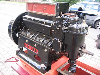
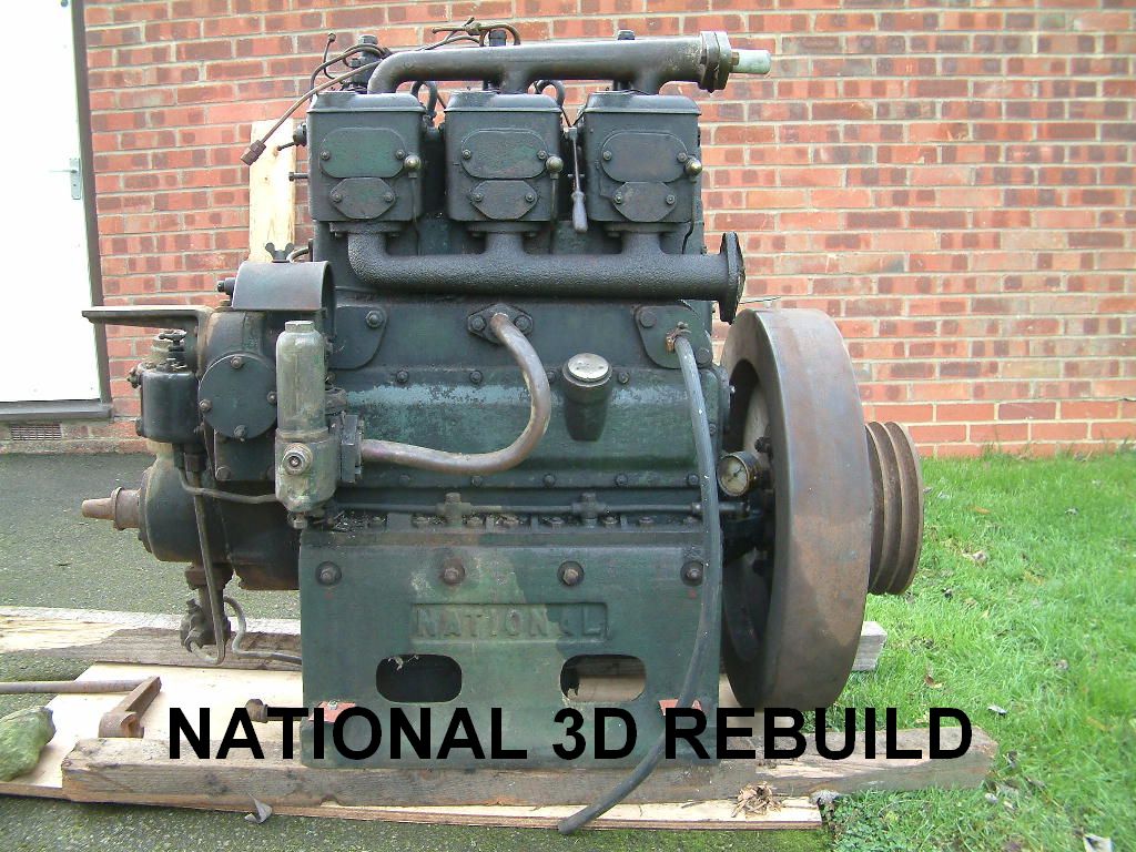
The result:


Now, it's not time to get to excited as its all got to come apart again, but it does give an impression of the finished article.

I also now know of a few studs that need to be replaced and a couple of nuts that are missing. Additionally it has helped me find a few places (on the machines surfaces of the castings) that need to be painted before final assembly as they will be virtually impossible to get too once assembled.

A useful exercise and it does raise the level of hope!

Saturday, 5 July 2008

Engine Mounting and Bugger!

A while back I posted an entry about the construction of the engine bed and the fun and games had with drilling the engine mounting holes.

Well…. I made a decision about the mounting method and have gone for a modern product call ‘TICO S’. A "High performance machinery mounting pad", according to the manufacturers.

It comes in various guises, but I bought a strip of the stuff 100mm wide (4" in old money) by the standard 12.5mm deep. I also bought some of their TICO S washers.

The engine is to be mounted on the TICO strip and the bolts have TICO washers at the top of the engine. This has effectively cushioned the engine between the TICO material and should absorb a lot of the vibration but still hold it firmly to the engine bed.

The ‘Bugger’ bit?

Well… Whilst carrying out this exercise I noticed an error in the engine bed manufacturing process.

I welded the cross members between the longitudinal members at the engine mounting points. This would give the frame the most strength/rigidity at the mounting points. Fine at the front (this will be effectively covered by the flywheel overhang). A problem at the rear though.

The National has a sump that is separate to the crankcase. The clearance from the bottom of the crankcase to the top of the rear cross member is 4.1/4". What’s the depth of the sump?… 5.1/4" ……. Bugger!


I’ve now got to ‘notch’ out at least 1" from the top of the rear cross member. A bit of an exercise if the engine bed had been built of wood, but its not. It’s built from 6mm structural steel!

It’s been a while since I’ve used a gas axe. Man the fire extinguishers!

Still, at least I’m dealing with these problems in the comfort(?) of the garage. Imagine trying to do it having just lowered the engine in through the roof of your boat on to an engine bed that had just been welded to the bottom plate of your Narrowboat!

Happy days!

Flywheel

'Flywheel'

It's quiet a boring heading I know, but I have finally attacked the flywheel.

Originally the engine had an industrial flywheel (as can be seen on the blog header). This would have been a problem as it did not have any teeth for an electric starter (the engine being hand start only). However, a suitable toothed marine flywheel that matched the crankshaft mounting was supplied with the engine.

So, as per usual, the task in hand was to remove all of the paint back to bare metal.

How much paint can a flywheel have on it! There were layers of the stuff!

There's a lot more surface area to a flywheel than you think. Several tins of paint stripper and many hours with a wire brush and the thing was cleaned up.

One thing it did reveal on the inner boss was the stamping 49909. Could this have been the engine number of the 'donor' engine? If it is; thank you 49909, because your flywheel is now going to be well and truly bolted to the front of 56214. And long may it remain there (mainly because its to blood heavy to get off!).

Of course, once you get all of the old paint off and get the metalwork cleaned up, you've got to put the new stuff on. The result is:

A nice big black shiny flywheel!


Oh........ and another thing. The previous entry was with regard to the water pump. Well, here's a picci of the finished item assembled in full. I think it looks great against the black of the engine (the picci doesn't do it justice and it looks better in the flesh)

Thursday, 19 June 2008

Water Pump

Really sorry for the lack of updates. I know its been the best part of a month. Unfortunately things like w##k and maintenance on the home have been taking a bit of a priority of late. I know its not good enough - but that's the fact's.

Anyway, what have I been up to. Not a great deal, but there has been a little tinkering hear and there when the opportunity arises.

The current semi project has been the water pump drive unit.

The water pump is a plunger type unit that is powered via the fuel pump cam shaft.

A set of skew gears turns the drive through 90 degrees and operates a brass plunger via an eccentric cam.

All very simple but, hopefully, very effective.

Obviously the first thing to do was to break it down in to its component parts so that every thing can be inspected and cleaned up.

In fairness, it was all in pretty good nick, so it then followed on with the usual (you know the score).

At the end of the task, another semi component is ready and wait for the great assembly process

I love the cam lubrication process. Remove cover by undoing brass wing nut, open the spring loaded reservoir cap and fill reservoir with oil. A wick feed then drips the oil down on the the 'big-end' of the plunger and trough via an oil way to the 'little-end' of the plunger.

Another little pre-start up job.

Once coupled up to the cylinder body, it will look the mutt's nutt's bolted to the side of the black beast.

I do need to make some new leather washers for the plunger. Anyone got any spare laderhosen?

Next up, I intend to attack the flywheel. It shouldn't be to much trouble apart from the many layers of paint and the sheer weight of the thing and the associated problems that that brings with it.
Watch this space!

Monday, 26 May 2008

Governor Case Re-build

Well, I've talked about it enough, so now it was time to actually do some work on the governor.
It's quite a lumpy bit of casing with a vertical shaft run direct from the crankshaft up through one side.

The large section at the top housed a set of spring loaded centrifugal weights and the shaft drives the oil pump at the bottom.

Obviously the first job was to strip it down in to its component parts. Then the usual cleaning up, etc, etc. Eventually it turns in to this:

The oil pump was in good condition and just needed a thorough clean up.
Once everything was cleaned up, all of the various component part that required painting had an initial coat of paint. Then it was time to put everything back together.

Ensuring the oil pump had the correct thickness of cover plate joint took a while. To thin and the gears were tight against the cover plate. To thick and there would be to much clearance between the cover plate and the gears which would result in a noisy and inefficient pump. The task was done by trial and error with multiple 0.5mm joints (all hand cut) until the correct thickness was achieved.

New joints where made for all of the other mating faces and, after a bit of fiddling around the final result:


Another bit ready to fit come the time of the great re-assembly.

Sunday, 25 May 2008

Photo's

Any regular views may notice that there are a few more photo links.

I had a bit of a sort out of the photo's and have put them in to 10 basic categories.

Ignore the Photo Bucket cr#p and feel free to have a look.

Please let me know if any of the links don't work.

Engine porn at its best!

Edited to add:

A gentle slap on the hand from Sarah (see comments). There are a couple of acknowledgements I should really add.

The photos of the 'National Works' are courtesy of Sarah (NB Warrior). See: http://d3national.blogspot.com/2007/12/national-works-aston-under-lyne.html

The 'Engine Pre strip down' and 'Initial strip down' are courtesy of Lionel Knight: http://d3national.blogspot.com/2007/12/well-i-think-i-may-have-added-some.html

I think the rest are mine.

Wednesday, 21 May 2008

End Bed

Well, it was a weekend of cutting, grinding and welding. A bit of a change from degreasing, cleaning, stripping and wire brushing!

The result - an engine bed all fabricated up and ready for the re-build.


Its basically fabricated out of 75mm x 150mm channel (that's 6" x 3" in old money). The ultimate plan is to rebuild the engine from the bottom up, direct on to the bed plate. Get the gear box setup and aligned and once all finished and tested, the whole shooting match get transported up to the boat builder and welded in to place direct to the base plate.

Once fabricated, it was time to drill the holes for the mounting bolts. 21" apart and 20" along, 3/4" holes. Using the old adage of measure several times and drill only once, checking the diagonals to ensure they where all perfectly aligned, it drilled some 4mm pilot holes.

Before stepping up to eventually drill the full 3/4" holes; I 'dropped' the bottom end with the mounting legs on to the frame. Theoretically, the pilot holes should have been right in the centre of existing 3/4" leg holes.

Were they buggery!

Remove the bottom end, double check all of the measurements on the bed. Yes, everything was true and square. 21" x 20" with equal diagonals.

Check the engine legs (not an easy task with 2/3 cwt of engine bed floating in mid air on the hoist). Hole centres are 21" x 20". Equal diagonals - NO! The engine legs are pi##ed.

Take the legs off the Crankcase. Yep, they're fine. All of the original locating dowels are in place and true and the legs cannot be put on the 'wrong side' because the dowel won't allow it.

Put the legs back on, bolt them all. Re-check the measurements. Still askew!

Because the pilot holes have been drilled, the only answer now is to get a 3/4" hole saw and (after clamping the engine base to the bed) drill down through the leg holes and straight in to the base.

So much for the science of measuring and drilling as per the 'factory measurements'.

Hey Ho!